Chimney technique

- General characteristics of chimney systems
- Chimney height
- Ventilation of chimney systems
- Expansion gap
- Support plate
- Cover plate
- Statyka kominów BRATA
- Selection of the diameter of the chimney
General characteristics of chimney systems
- Each building in which the heating boiler is installed should have an effective flue gas exhaust and ventilation facilities.
- Sucking action of smoke, flue gas, and ventilation ducts is due to the pressure difference: of the cooler air from the outside and the warmer, lighter air from inside the building.
- Modern chimney systems should be characterized by:
- resistance to condensate exposure,
- resistance to possible soot fire,
- tightness, providing adequate draught and safety of users.
- The minimum inside diameter of the chimney must not be less than 140 mm (not applicable to condensing boilers with closed combustion chamber).
- It is recommended to build chimneys of circular cross-section of smoke and flue gas ducts, as characterized by lower friction resistance when gas flows. The advantage of ducts of such a cross-section is also higher effectiveness of their periodic cleaning.
- Chimney cross-section areas should be adapted to its height, boiler power and type, and the type of fuel used.
- Chimney duct outlets should be accessible for cleaning and periodic inspection. To this end, the roof should be made with permanent access paths to chimneys.
- It should be ensured that the cleanout doors were in a position suitable for removal of impurities from the chimney and their distance from the nearest combustible material should be a minimum of 30 cm. Whenever needed to use additional cleanout door above the flue tee (e.g. at the attic), the combustible material floor should be covered with non-combustible material (e.g. sheet metal, stone or ceramic tiles). In the case of a considerable height of the chimney above the roof or high roof pitch, a very practical solution is to install an additional cleanout, approx. 100 cm above the roof.
NOTE! Installation of this additional cleanout should be agreed with your local chimney inspector.
Chimney height
- Effective chimney height measured from the flue tee to the outlet above the roof should be:
- for gas boilers, a minimum of 4 m.
- for oil-fired boilers a minimum of 5 m.
- It is recommended that chimneys placed outside the building were thermally insulated and combined with a wall using brackets anchored in the wall (Fig. 1). The minimum number of brackets – 2 pcs.; maximum spacing of brackets – every 3 m.

- Height of the chimney above the roof must meet the following conditions:
- flat roofs with an inclination angle of the roof slope to 12°, the outlet of the chimney should be at least 0.6 above the roof ridge, regardless of the roof structure – Fig. 2.a

- for steep roofs with an inclination angle of the roof slope above 12° and easily inflamed covering, duct outlets should be at a minimum height of 0.6 m above the level of the roof ridge – Fig. 2.b

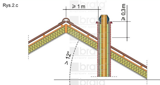
- for steep roofs with an inclination angle of the roof slope above 12° and non-combustible or flame retardant covering, duct outlets should be at a minimum of 0.3 meters above the roof surface and at a distance measured horizontally from this surface of a minimum of 1.0 m – Fig. 2.c
- flat roofs with an inclination angle of the roof slope to 12°, the outlet of the chimney should be at least 0.6 above the roof ridge, regardless of the roof structure – Fig. 2.a
- The roof with a slope greater than 12° should be treated as an obstacle to the proper functioning of the chimney. Therefore, depending on the location of the chimney against the highest element of a building constituting an obstacle (curtain), chimney flue outlets should absolutely be:
- at least 0.3 m above the upper edge of the obstacle (curtain) for chimneys located at a distance of 1.5 m from the obstacle – Fig. 3.a
- at least at the level of the upper edge of the obstacle (curtain) for chimneys located at a distance of 1.5 to 3.0 m away from the obstacle – Fig. 3.b
- above the plane derived at an angle of 12° downward from the level of the highest obstacle for chimneys located at a distance of 3 to 10 m from the obstacle – Fig. 3.c

Ventilation of chimney systems
- All the rooms, including the basement and attic, should have the air intake and exhaust ventilation ducts routed through the roof. In the room, where a heating boiler is installed, there should be supply ventilation opening of the area not less than 200 cm2, its bottom edge should be not higher than 33 cm above the floor, and exhaust ventilation opening of the area not less than 200 cm2 placed as close to the ceiling as possible.
- Ventilation ducts, as opposed to flue gas and smoke ducts, are finished with side outlet holes directly under elements covering the chimney. To avoid undesirable air flow turbulence, it is recommended to make two holes on opposite walls of a duct – Fig. 4.a. This recommendation does not apply to the configuration of the chimney SW + W2 and above. In these cases, the wall separating ducts in a ventilation brick shall not be infringed – Fig. 4.b.

Expansion gap
- A chimney is a free-standing structure. Therefore, it is not allowed to bond permanently the chimney with structural elements of the building, leaving a gap of 5 to 10 mm – Fig. 5.
- A chimney shall not directly adhere to flammable wall surfaces. Therefore, you should keep a distance of at least 5 cm, and the space must allow for air circulation – Fig. 6.

- When passing the chimney through the ceiling, the expansion gap should be:
- for a non-combustible ceiling, 3 cm – Fig. 7.a
- for a combustible ceiling, 5 cm – Fig. 7.b

- The smoke conduit passage through a flammable wall must be protected with non-combustible materials within a minimum radius of 15 cm – for example, with mineral wool – Fig. 8a. The passage of the smoke conduit through a non-combustible wall should be separated by movement joints with mineral wool along the entire length of the passage in order to eliminate stresses – Fig. 8b.

- When connecting a steel smoke conduit with a ceramic flue tee, their expansion joint is absolutely needed:
- for gas and oil boilers with low flue gas temperature, the expansion gap should be approx. 3 mm, and a special ceramic rope resistant to high temperatures should be used to fill it, or it may be filled with a flexible, heat-resistant silicone
- for solid fuel boilers, the expansion gap should be 5 - 10 mm, and a special ceramic rope resistant to very high temperatures should be used to fill it – Fig. 8a and 8b.
- for classic fireplaces and fireplace inserts, the expansion gap should be 5 - 10 mm, filled with a ceramic rope. We recommend that in this case, to use a 45° flue tee – Fig. 9.
 Before inserting the smoke conduit to the flue tee, wrap its end with a ceramic rope. Recommended rope dimensions are included in Table 1. Ceramic ropes are offered by our company.

NOTE! It happens that on the construction site, it is necessary to temporarily connect a furnace (e.g. wood burning stove) to reheat rooms. In this case, care should be taken to have the smoke conduit (steel pipe) long enough to prevent direct exposure of the ceramic flue tee to the flame. Connecting this type of a furnace with too short smoke conduit may result in thermal shock resulting in a damaged (cracked) flue tee.
Support plate
- In order to finish a chimney with clinker bricks, use reinforced concrete support plate – Fig. 10. Our offer includes prefabricated support plates for chimneys type: S – Fig. 10.a, SW – Fig. 10.b.
 However, for other configurations: for example. SW + W2 (Fig. 10.c), make a support plate on-site using an expanded polystyrene formwork offered by our company. Reinforcement of the supporting plate poured directly on-site should be made according to the following guidelines – Fig. 12.
 NOTE! Reinforcing mesh must necessarily be located up to 2 cm from the upper surface of the plate. Keep in mind that B 20 concrete obtains its full strength after 28 days. When brick-lining the chimney, leave free joints in the first and last layer of bricks with a purpose of brickwork ventilation.

Cover plate
- To properly protect the chimney structure against weather conditions, use a cover plate. Our offer includes cover plates for steel and concrete chimneys, Type S – Fig. 13 and SW – Fig. 14. Steel plates may be made by our company in any indicated by the client RAL color.
 Cover plates should be mounted using concrete mortar. For mounting steel plates, use mounting adhesive (preferably a polymer glue). Additionally, we recommend to use anchors – Fig. 15.
 If necessary to use cover plates for another set of chimney ducts, steel plates are manufactured by our company on request. In contrast, concrete plates should be self-made at a construction site according to guidelines given – Fig. 16.

 To make a concrete cover, use B 20 concrete. The hole made using a polystyrene template should be positioned exactly along the axis of the ceramic pipe crowning the chimney. The upper surface of the cover plate should have an incline away from the centre to the sides. The cover plate, made at the construction site, should form a chimney hood of a minimum width of 6 cm. Before mounting the cover plate on the chimney, you should make cuts (drips) at the underside of the plate at a distance of 2.5 cm from its edge – Fig. 16.
Statyka kominów BRATA
- The BRATA chimneys are characterized by high stability of the structure. This allows the construction of our chimneys up to the total height of 25 m, measured from their base, provided that their height above the roof corresponds to the values shown in Table 4.
 NOTE! To use the table, it is necessary to provide a lateral support for the chimney in the roof of the building – Fig. 17.
To ensure the horizontal rigidity of the chimney at the height of its passage through the roof and at same time to separate the chimney by movement joints from the building structure, make an appropriate mounting to the roof structure. Using angle or channel section profiles, make a steel brace attaching the chimney and using screws fasten it to the beams of the roof truss. The steel brace should be mounted above or below the beams. The height, h of the chimney above the roof according to Table 4.
- Proper stability of the BRATA chimneys protruding above the roof when exceeding the values recommended in Table 3, may be achieved by additional reinforcement. Reinforcement is made of steel bars Ø12 mm, which are placed in designed for this purpose holes Ø30 mm located in chimney bricks. To facilitate additional reinforcement of the chimney at the construction site, we recommend to use ready-made reinforcement bars Ø12 mm with threaded ends and steel fasteners with internal M10 thread – Fig. 18.
 Reinforcement bars, which are offered by our company have a standard length of 100 cm. After mounting the reinforcement as required for a specific length of the chimney, the last section should be cut so that its end is lower by approx. 25 cm from the end of the chimney. Reinforcement bars should be based on special plugs previously pressed into holes of chimney bricks at the proper height of the chimney – Fig. 19.b. Recommended length of the chimney reinforcement should be twice its height above the roof surface (e.g. 4 m for a chimney of the height of 2 m above the roof surface, 6 m for a chimney of the height of 3 m above the roof surface) and its bottom to be supported at a distance of not less than 0.75 m from the lower chimney support in the roof of the building – Fig. 19.
 Connected to each other and located in the four holes of the chimney casing, the reinforcement bars should be filled with cement grout – Fig. 19.a.
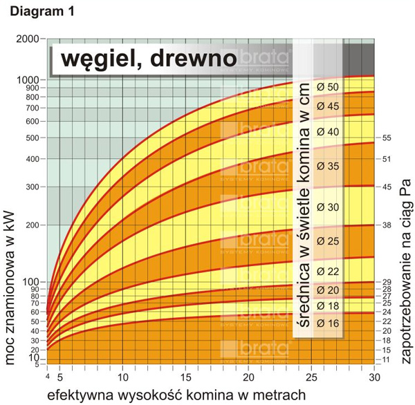
Selection of the diameter of the chimney
- BRATA Chimney Systems may be used for the construction of flue gas and smoke ducts, discharging exhaust gases from solid fuel fired boilers and stoves, and modern oil or gas boilers with an open combustion chamber. Depending on the chimney height and the technical parameters of a boiler or fireplace, and above all on its heating power, a designer of the heating system selects the diameter of the flue pipe. Simplified procedure is given below on diagrams.